- A+
In high-performance and luxury utility vehicle platforms like Land Rover, thermal management extends far beyond the primary engine radiator. Modern drivetrains generate enormous thermal energy under heavy load, stop-and-go transit, and off-road trailing. When automatic transmission fluid (ATF) or engine oil temperatures cross critical thresholds, fluid oxidation accelerates exponentially, leading to premature valve-body wear, clutch slippage, and eventual powertrain failure.
For global aftermarket importers, fleet operators, and distribution networks, sourcing heavy-duty cooling components that match original equipment specifications is crucial. Below is a technical analysis of the APCF-52357 8-Row Auxiliary Oil Cooler Kit, engineering to match the exact form, fit, and thermal performance of the industry standard MAHLE BEHR OSA014-8-BA system.
The Engineering Challenge: Managing Fluid Thermal Degradation
Automatic transmissions and turbocharged engines rely heavily on stable fluid viscosities to maintain hydraulic pressures and boundary lubrication.
- The Vulnerability Point: Standard factory cooling loops are often integrated directly into the radiator’s cold tank. While compact, this setup can become overwhelmed during sustained high-torque demands (such as towing or low-range crawling), causing coolant and transmission fluid temperatures to spike simultaneously.
- The Solution: An auxiliary, standalone heat exchanger positioned in series with the factory loop. U APCF-52357 functions as a dedicated fluid-to-air cooling circuit, shedding excess BTU loads before the fluid returned to the sensitive internal components of the transmission or engine block.
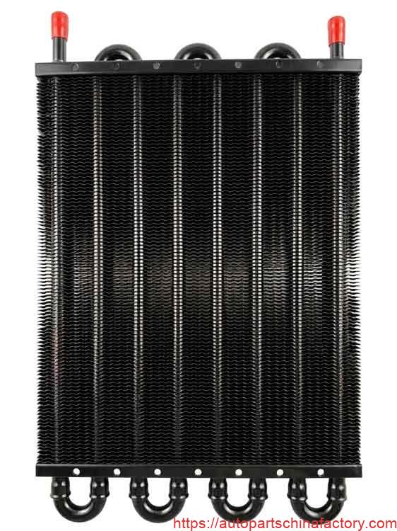
Technical Deep-Dive: Core Design and Dimensions
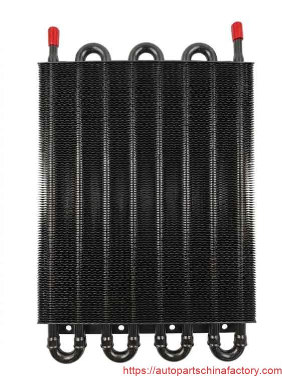
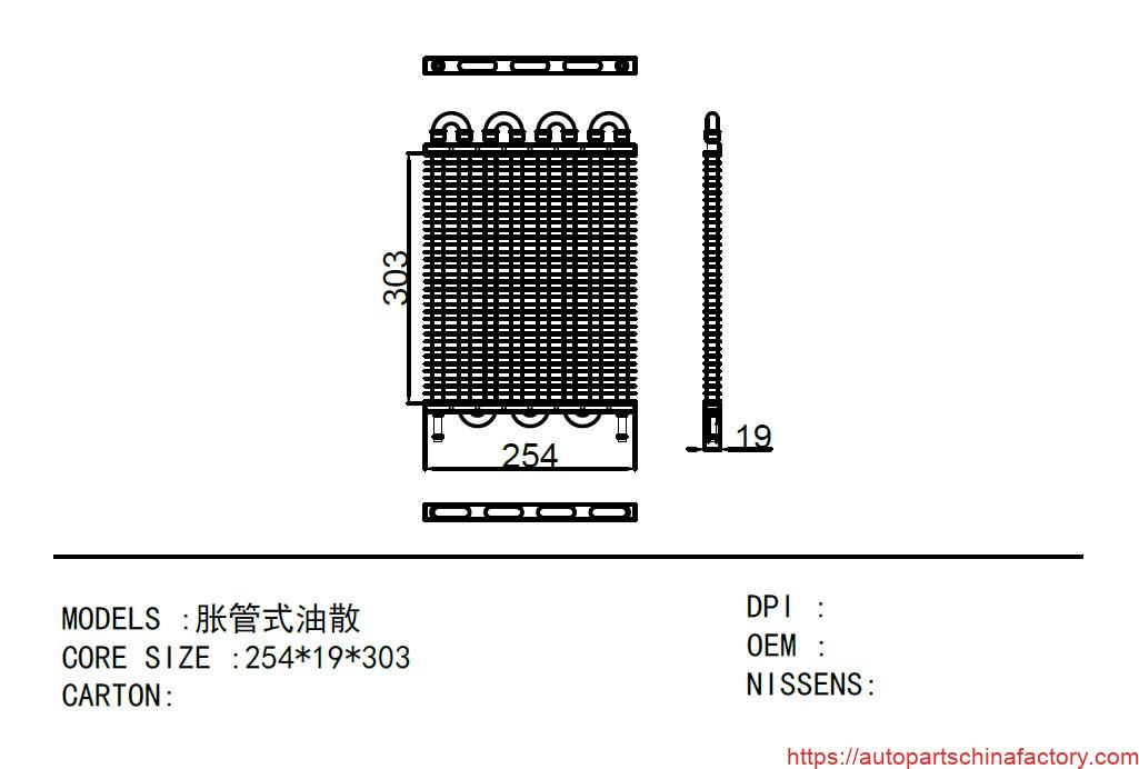
The core configuration of the APCF-52357 is engineered with a Tube & Fin Expansion Style (胀管式油散) architecture. This design relies on copper or high-grade aluminum fluid tubes mechanically expanded into high-density corrugated cooling fins to guarantee 100% surface contact, maximizing conductive heat transfer.
+--------------------------------------------------------------------------+
|                       TECHNICAL PERFORMANCE METRICS                      |
+--------------------------+-----------------------------------------------+
| Parameter                | Measurement & Material Specification          |
+--------------------------+-----------------------------------------------+
| Grid Configuration       | 8-Row Horizontal Pass                         |
| Core Dimensions          | 254 mm x 19 mm x 303 mm                       |
| Core Thickness           | 19 mm                                         |
| Core Material            | High-Grade 3003 Aluminum Alloy                |
| Core Pressure Resistance | 130 kg/cm² (127 Bar / 1,850 PSI)               |
| Hose Material Structure  | Dual-Layer Technology (Inner: NBR / Outer: CSM)|
| Hose Pressure Resistance | 70 - 80 kg/cm² (68 - 78 Bar / 1,000 - 1,140 PSI)|
| Primary Cross-Reference  | MAHLE BEHR OSA014-8-BA                        |
| Application Segment      | Land Rover / Universal Auxiliary Duty         |
+--------------------------+-----------------------------------------------+
Key Engineering Advantages of the APCF-52357 Core:
- Multi-Pass 8-Row Fluid Dynamics: Fluid travels through eight individual cooling passes. This maximizes the dwell time of hot oil within the laminar airflow zone, achieving a superior temperature drop per pass compared to lower-density 4-row or 6-row alternatives.
- 19mm Ultra-Thin Profile: The slim 19mm core footprint allows workshops to stack this unit seamlessly in front of the primary A/C condenser and radiator assembly without restricting necessary ambient airflow to the rest of the cooling stack.
- Corrosion-Resistant Matte Finish: The external surface is treated with a specialized matte black thermal coating that resists oxidation, stone-chipping, and road salt degradation without forming a thermal insulation barrier.
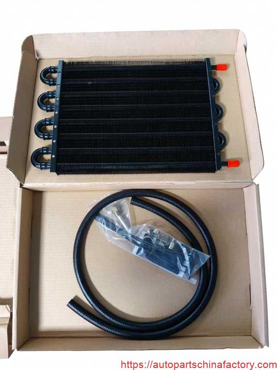
All-In-One Workshop Installation Package
For B2B procurement networks and parts wholesalers, complete package integration reduces delivery errors and workshop turnaround times. The APCF-52357 is supplied as a complete standalone installation system rather than a bare core.
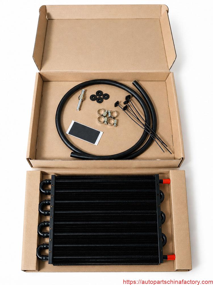
Complete Bill of Materials (BOM):
- Premium 8-Row Core: Equipped with heavy-duty structural mounting brackets pre-stamped along the side flanges.
- Reinforced High-Pressure Fluid Hose: Formulated from durable nitrile/EPDM polymers to withstand high-temperature fluid cycles and prevent degradation from synthetic oils.
- 4x Heavy-Duty Interlocking Zip Straps: Designed for rigid pass-through mounting through the existing radiator cooling fins without requiring custom iron brackets.
- 4x Cushioned Foam Backing Pads: Placed between the cooler core and the vehicle's structural components to dampen harmonic vibration and protect against abrasion.
- 4x Stainless Steel Worm-Gear Hose Clamps: High-torque tensioning clamps that provide uniform clamping force around the inlet/outlet nipples to eliminate high-pressure fluid leaks.
- 1x Iron Connector Fitting Adapter: Precision-machined interface component to ensure secure fluid line integration into the vehicle’s original oil lines.
Sourcing & Packaging Optimization for Global Logistics
For international distributors managing container loading (20GP/40HQ) and warehouse logistics, structural integrity during transport is critical. Fragile aluminum cooling fins are highly susceptible to shipping damage if poorly secured.
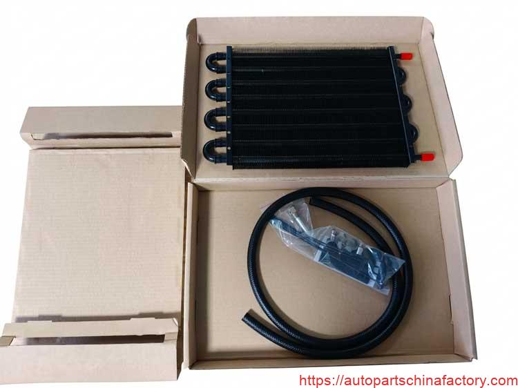
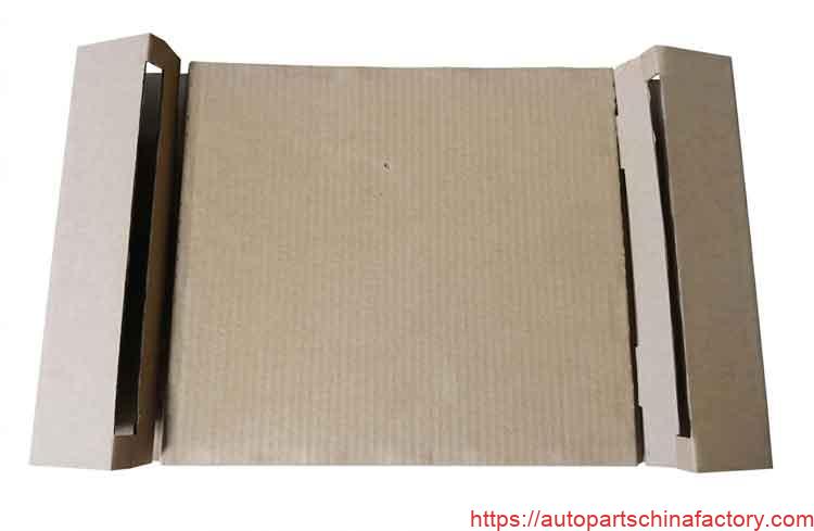
- Internal Fin Stabilization: The APCF-52357 kit utilizes a precision-cut, industrial corrugated cardboard stabilization sleeve that encloses the core, keeping the delicate cooling fins isolated from heavy accessories like hose lines and steel clamps inside the box.
- Neutral Kraft External Box: Delivered in standard, unbranded, high-density kraft shipping cartons. This allows distribution networks to easily apply custom barcoding, white-labeling, or regional retail stickers without repackaging overhead.
- Industrial Pressure Testing: Every unit undergoes a rigorous post-brazing/post-expansion high-pressure submersion test to ensure structural soundness, protecting against localized pinhole leaks or end-tank separations under high-flow operations.
Professional Installation Guidelines
For service networks and mechanical workshops, adhering to these technical layout parameters will ensure maximum thermal efficiency:
- Laminar Airflow Positioning: Mount the oil cooler assembly directly in front of the primary radiator fan configuration. Ensure a minimal air gap (using the provided foam cushioning pads) to utilize the suction force of the vehicle's engine fan during low-speed crawling.
- Port Configuration: Whenever possible, mount the unit with the inlet/outlet ports facing sideways or upwards. This prevents air-locking within the 8-row core matrix and guarantees complete internal fluid submersion for optimal heat transfer.
- Fluid Level Adjustment: Because adding an auxiliary circuit increases the total volumetric capacity of the transmission or engine oil system, remember to top up the vehicle's fluids according to OE standards after priming and heat-cycling the new circuit.